Delta Robot

Just a quick post to show what I've been working on.  First, inspiration came last year from here:

http://reprap.org/wiki/Rostock

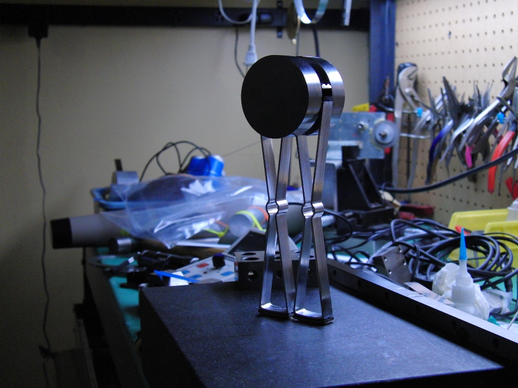
A parallel robot; a "linear delta" configuration.  I'd studied this and designed several variants back in '97 on my way to creating the KAOS robot.  I was fascinated with the parallel robots, but the controls were going to be difficult to a level I wasn't prepared for at the time.

A few years later, I realized I'd be able to lean on my new friends at Delta Tau to create a control kinematic for anything I could come up with, but in KAOS, I was after something different: linear behavior, and integer relationships between differentially moving carriages, and servo tuning consistency no matter where you are in the addressable volume.  Parallel robots are none of that, but let's just revel in the beauty of them anyway.

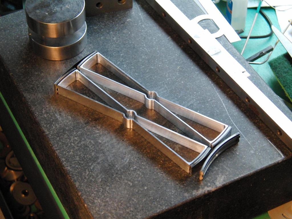
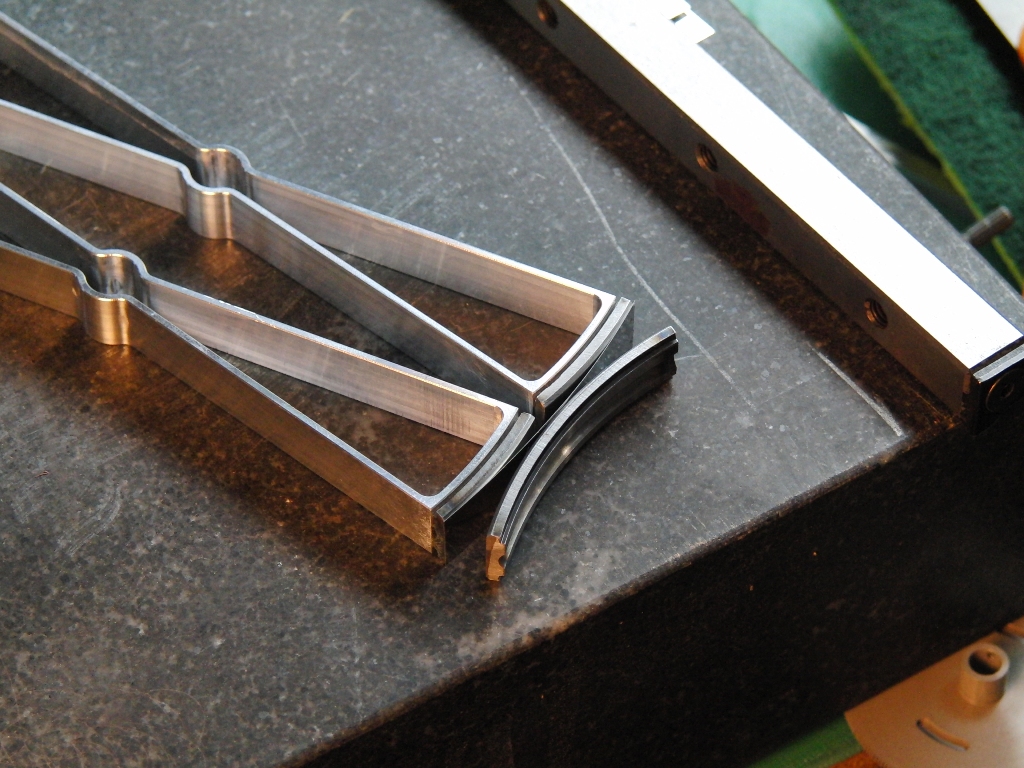
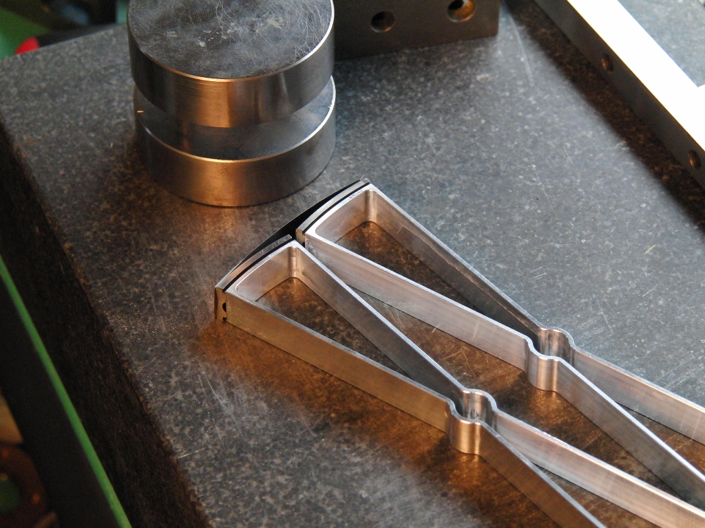
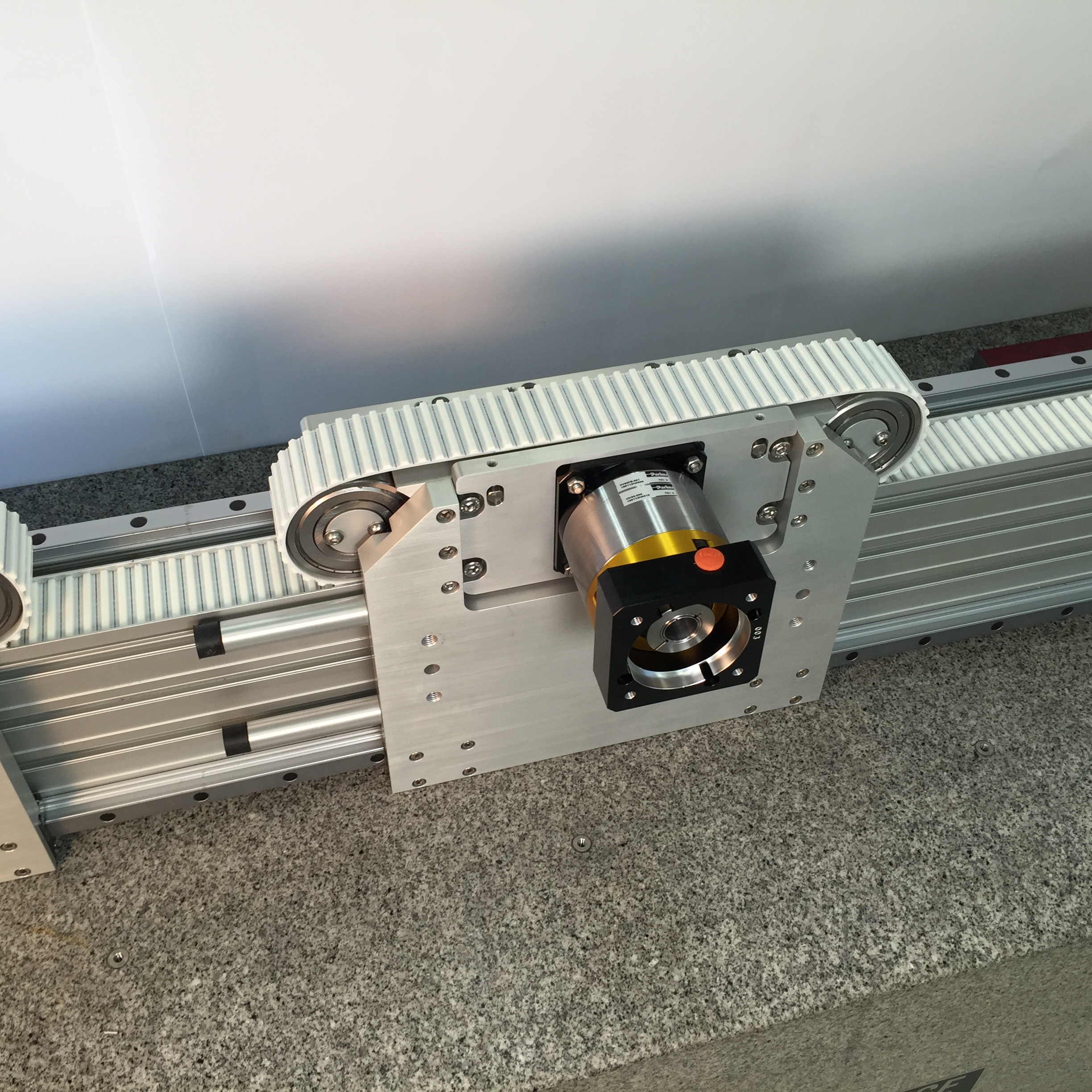
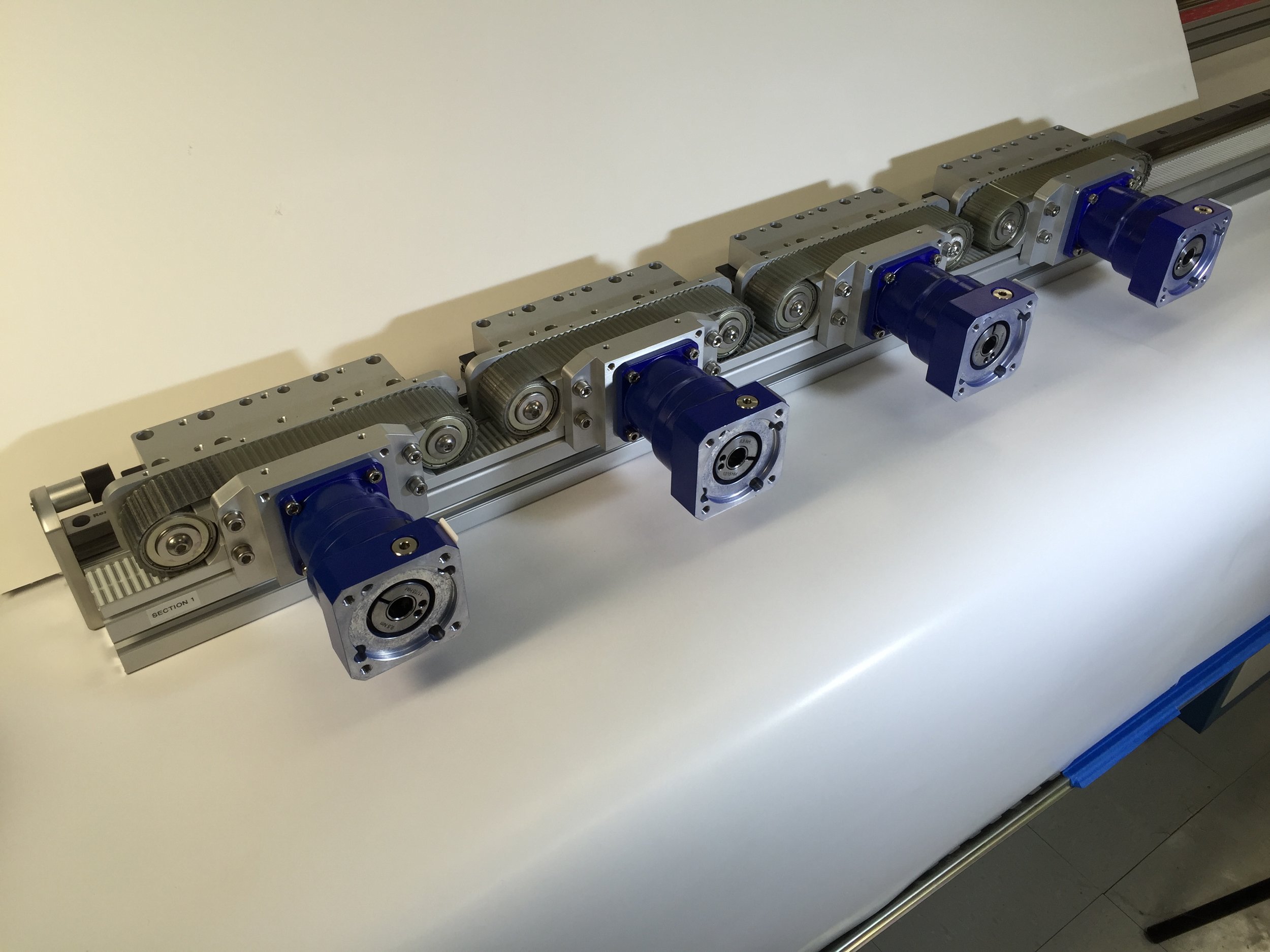
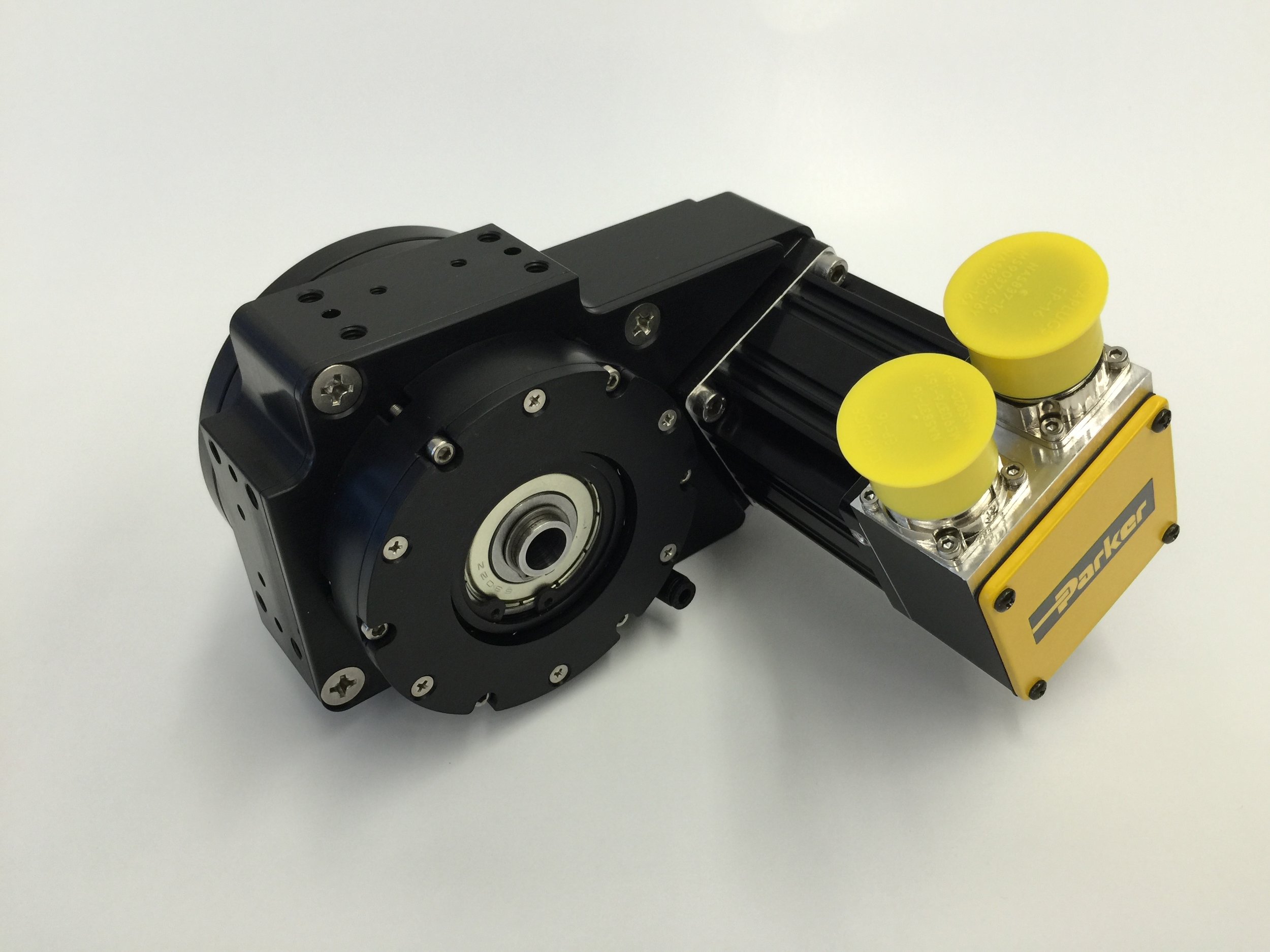
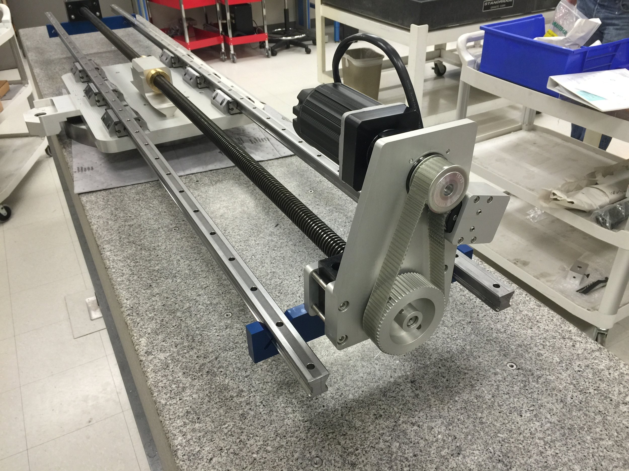
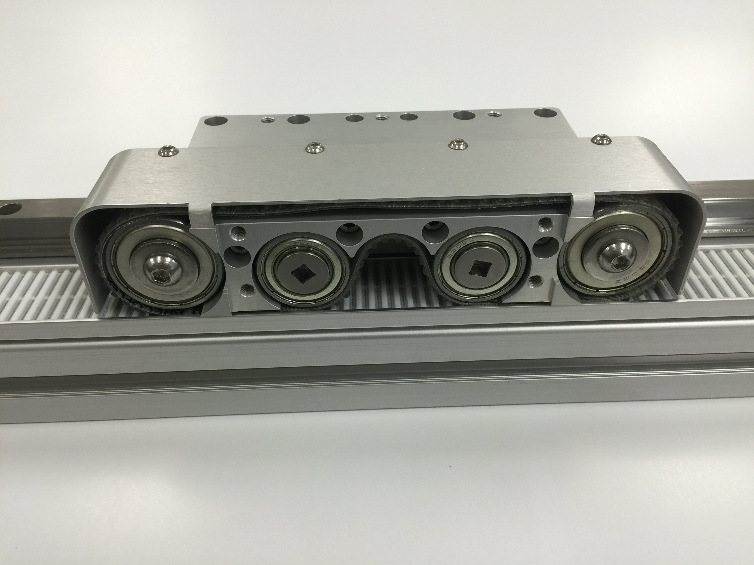
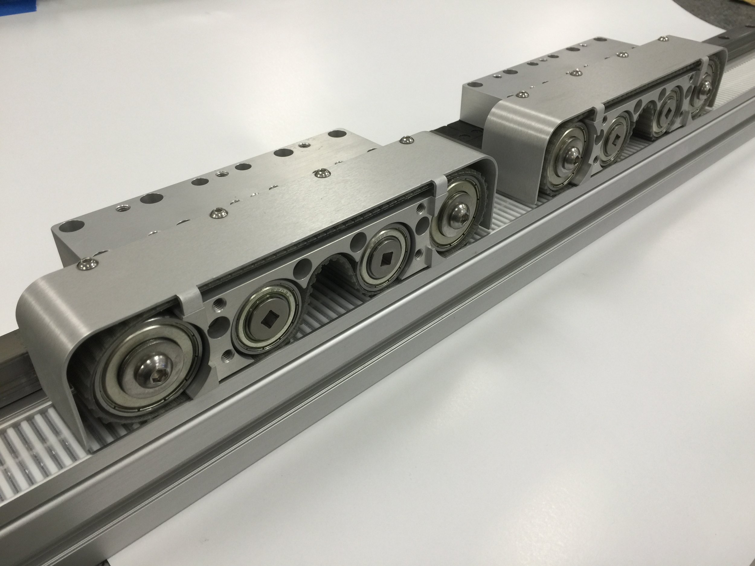
Once a design is done, the amazing prototyping capability of 3d printing takes over, and hardware becomes real!

KAOS 3D

This one was a three axis KAOS robot pick and place with five meter per second (ludicrous speed, capable of it, but unnecessary), and (amazingly and unnecessarily) five nanometer resolution.  Our customer's machine did not go into high production, but the robot worked great.  Delta Tau made the coordinate system easy work.  A single line in the config file was enough to make this kinematic accept Cartesian commands.

With ServoBelt drives instead of linear motors, this one can be both economical and still have the lowest possible moving mass for a three axis stage.

Air Motor Prototype works great!


This is a first run of a small 8-cylinder air motor prototype using my new radial piston architecture.  Sorry I can't talk too much about how it works yet.  It is quite simple and can be variable displacement while running, and is inherently balanced.  It will be good as a pump or a motor and is highly scaleable.  The big dream for it is use in compressed air vehicles.  The smaller dreams are for air grinder spindles and counterbalances for Bell-Everman Z axis motion.

First ornithopter wing warping demo

I'm embarking on an ornithopter project.  

This is an initial test of a neat wing warp mechanism.  Warring for time in my head are two types of flyers, VTOL like a hummingbird, or more of a soaring type.  We'll see how it shakes out.  

Coming next is an expanded demonstrator of the wing warp method, which is very cool, if I do say so.  The more I think on it, the deeper it goes, which is what I live for.  It's all about the process, man.  Sometimes I've just got to put some things together to see if my mind's eye is calibrated or not!

I've been mentally designing wings for myself since I was a teen.  My career has been all about light and powerful actuators and power transmissions, and deployable and dynamic structures for space.  That being the main hurdle for something like this, it's time again to start thinking about all that goes with the power source, and eventually make myself a flying ornithopter.  

Much has been done over the centuries, not much of it elegant or particularly practical.  Human power has worked, but certainly not practical.  Powered man carrying ornithopters have worked, but not very elegant or compelling.  There's very nice work being done making bird and insect like spy drones, which is far easier than a man carrier, to be sure.

What got me back into this was Jarno Smeets recent hoax video of "human birdwings".  In a way, I was glad it is a hoax, as my first reaction was "Damn, someone beat me to it!"  Not really reasonable, because I didn't work on it seriously in the first place.  My next reaction was "I know how to do this, so why wouldn't I?"  And I feel that now the race is truly on, since I am certainly not the only one inspired by this.  I think I've got the method of getting power to the wings in an elegant and failsafe way.  Making RC models as a first step will be fun!

Playoff round

Rules for the playoff were:
90 seconds to set up and fire one shot into a reduced size hole
60 points for a swish
50 points for hitting the edge and in
30 points for bouncing off the top

We tried to adjust backward for a swish by looking at the videos of the first run. Unfortunately, I should have videoed it from the side. We didn't know it would be important later! One team swished, another lipped and in, we bounced off. So first and second were set.
Jocelyn accosted the director to make sure there would be a runoff for third against the two other teams that bounced the top.

JPL Invention Challenge, our team going to the finals!

We competed at Manual Arts High School against 54 other teams last Saturday.  Not a great showing compared to all of our practice sessions, sinking one and two off the lip for a score of 110.  Held on to second place through the first 16 or so teams.  Went to lunch at Fillipe's for some amazing French dip sammiches, then came back to find we were out of the trophy race, but found out later that we were going to the finals anyway.  Between the two venues, there were only 6 teams with scores higher than us, but several like us at 110 points.
In practice before our time slot, we hit 8 for 8, then moved to the competition area, which was sloped in two directions!  I do not think that was the killer, though.  Our trigger mechanism, if you can call pulling a loop off of a hook a mechanism, has a bit of sensitivity to technique.  That's something we will fix this weekend for the finals on the 9th of December.
My team is great!  Hats off to the gang and our fearless physics teacher leader, Jarrod Bradley!

San Marcos Engineering Team JPL Challenge first test

A small group at San Marcos High is doing the JPL challenge; a machine that kicks a football into a trashcan 5m away, over a 2m barrier.  I am enjoying advising the students on the project!

I find it very helpful to do little tests like this, so that if we were to calculate the metrics of this motion, we will have a real life verification of our math model, or point out where it is deficient. 

This was a good shot, maybe a little low, but just about dead on the 5m distance.  Students can make measurements from this video for angle of inclination (look to the bookshelf in the background for a vertical line reference), and determine acceleration of the ball and the velocity of Mr. Bradley's fist at impact.  The video is shot at 300 frames per second, so check what frame rate your computer is playing, divide 300 by the frame rate to get the time factor.


POLAR MINI CNC

The polar CNC is getting closer to full production ready. Our customer is making their own enclosures and HMI panel, so we have that to create that as well for our metal cutting version. I think that before I put this out there as a full cnc, I'll want to have a solid spindle and some sort of tool changer available. Lots to do, so it's good to be a subsystem for now.
Mike

Sent from my iPad

ServoBelt goes Semicon (again)

This is a set of ServoBelt stages stacked to be an XY for a semiconductor application.  This video is just a burn-in move. The critical move of 12mm can be done in 180msec, settled to 5um.  Payload is 34 lb.  Motors are Teknic NEMA34 4-stack on the bottom and NEMA23 4-stack on the top, with Teknic Eclipse 350R amplifiers, and Renishaw RGH41 linear encoders.

Inverted Cycloid Pendulum

As I progress toward building a unique clock, it occurred to me that the "rodless" cycloid pendulum I had previously built could have supports of virtually any length.  What has come of it is a very interesting inverted pendulum which I will be testing over the Thanksgiving holiday to see how isochronous it is.  The bob still follows a cycloid path, and will have a (roughly) 1.2sec period.  The supports however, require a different treatment to make them isochronous at that period, considered alone, without the bob.  That is an upcoming experiment.

This hardware is simple breadboard stuff, using segments of a 6.75" diameter bearing race, which will eventually all be replaced by jewel shoes among other exotic materials.  I plan to build 6 clocks, one for each of the artisans that contribute to the case, the faces and the machine work.  I will plan on 2-3 to sell at some point.  This whole project will be years in the making, as I will be designing a completely mechanical movement that I hope will be as unique as the pendulum itself.

This is a very satisfying engineering exercise!