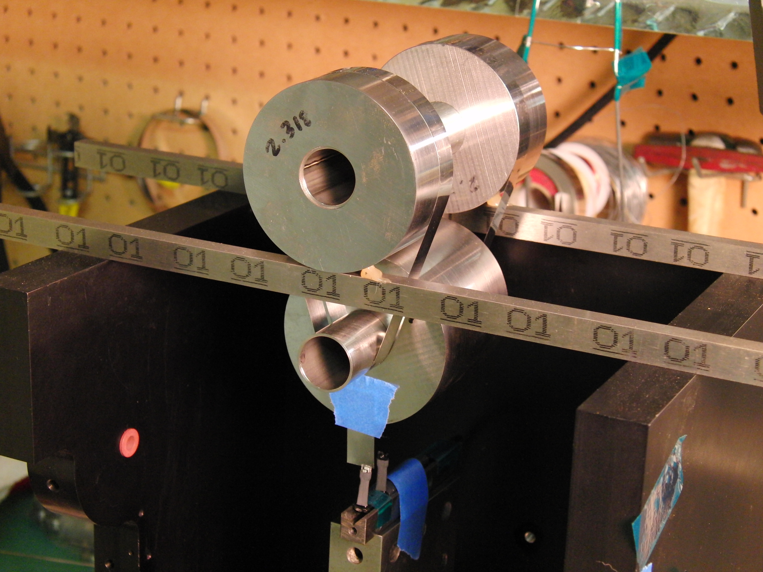
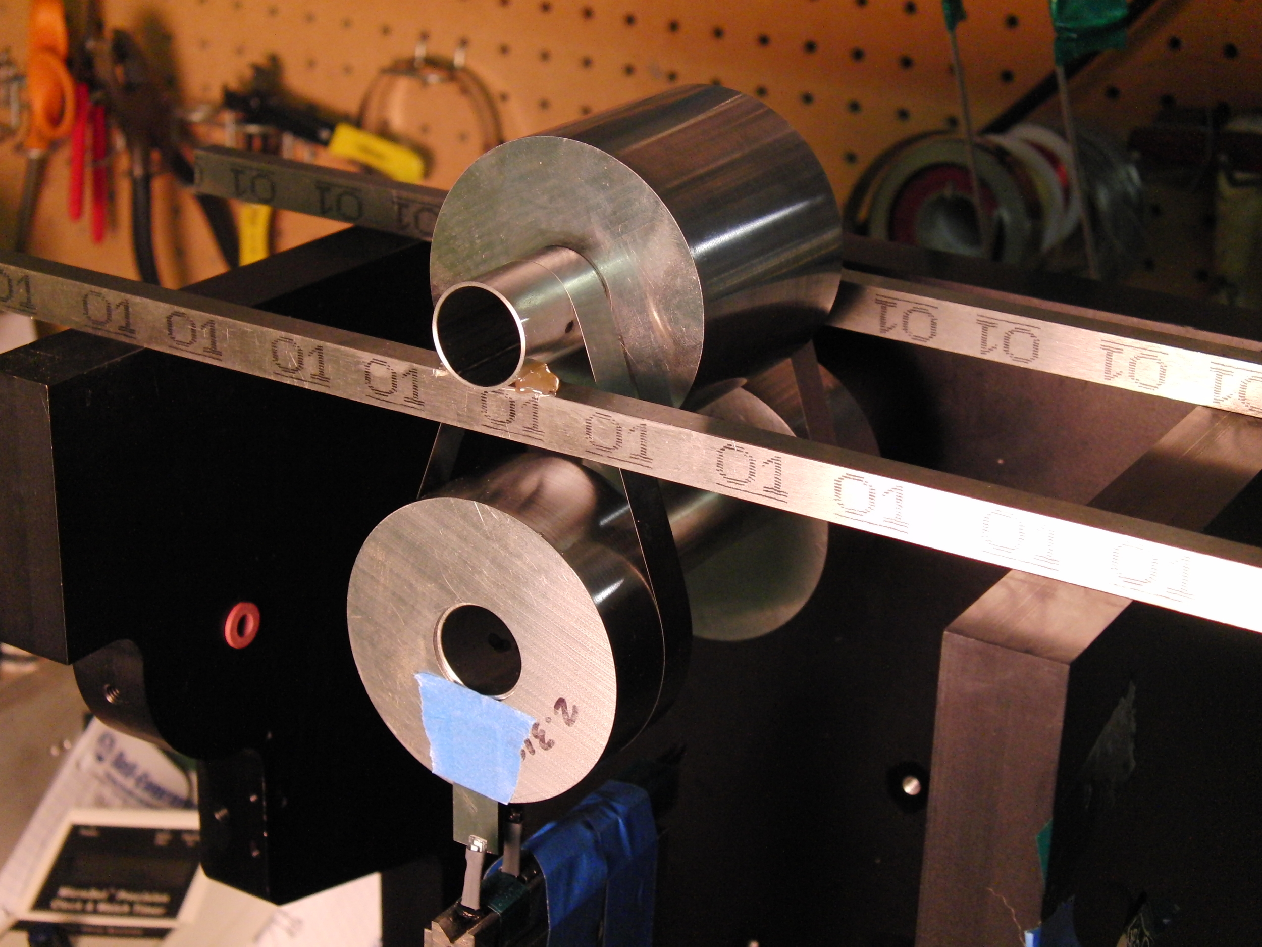
This rig has two identical stainless bands for a suspension. It is like a belt speed reducer, with the bands running from large diameter at one end to small at the other. The two bobs are less than .0002" different in diameter and their faces are parallel to the same degree by kiss grinding. The thicknesses are such that each bob, though one is made of two disks on the ends of a tube and one a single piece in the middle of an equivalent tube, are the same weight, that is to less than .001 lb. which is the resolution of my scale.
This can be set up for two cases, one where the bob's apparent moment of inertia (about it's center) is roughly ten times what it would be if rigidly attached to a rod, if there were one. In the other, with the small suspension diameter above, the local inertia is one-tenth of rigidly attached.
What it does is allow me to verify my math model of variable inertia bobs. One interesting aspect of it is the high inertia case can be shorter than a normal pendulum for the same frequency. I'd say another neat thing is that it follows a perfectly circular path, until one considers centrifugal deflection of the bands, but that would I'm sure fail as a theory on close inspection. I predict that it will be no more determinate than a knife-edge, but maybe more than a conventional band suspension, where bend radii are not enforced.
I've just gotten the flexure bands made, and have not made the support clamps yet. There's no meaningful data to be gotten yet, since, as much as I love my hot glue gun, it fails as a rigid mount. Look closely at the high inertia case and you can see the upper hardware moving. Bad show, that!